CategoriesCalendarArchivesQuicksearchSyndicationStatisticsLast entry: 2012-09-11 21:41
38 entries written
446 comments have been made
27 visitor(s) this month
1 visitor(s) today
2 visitor(s) online
Powered by
|
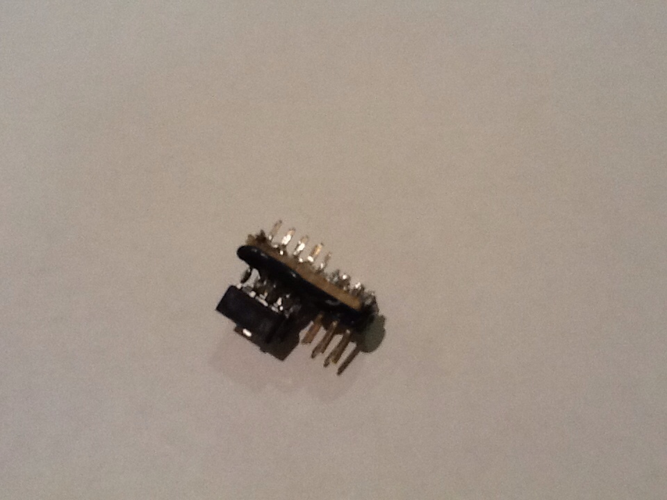
Sunday, February 26. 2012Monday, February 13. 2012Instrument Tuner - Programmable Filter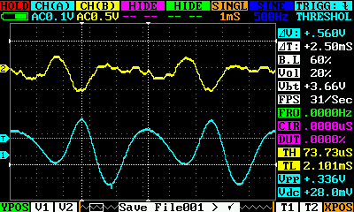 Cleaning up the waveform : before (yellow), after (blue). When I last looked at my musical instrument tuner, I was having difficulty with real-world waveforms from the instrument : all the harmonics meant that zero-crossing analysis wasn't accurate for capturing the fundamental frequency. This post describes my approach to solving that problem in the analogue domain - so that I don't need to worry about fast A to D conversion (although that would be an interesting problem in itself). The standard approach is to implement a low-pass filter, with the stop frequency tuned around the desired fundamental, to get rid of those troublesome harmonics. A passive filter would only achieve 6dB/octave roll-off, which is unlikely to be enough. And you can't sensibly cascade passive filters to improve that. Time to roll out the op-amps, and implement active filters, which are easily cascadable, and in the simplest form, are usually 2nd order so 12dB/octave. Cascading two of those together should give 24dB/octave, which should be plenty of attenuation. Continue reading "Instrument Tuner - Programmable Filter" Wednesday, February 8. 2012SPI addressing with minimal pins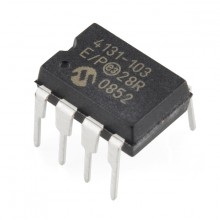 I picked up some digital potentiometers, partly as a building block for making a programmable filter for the ukulele tuner, but also just to play around with, as they seem pretty cool. They act exactly like a traditional potentiometer (i.e. there's an end-to-end resistance of 10KΩ, with a 'wiper' that can travel from one end of the resistance to the other), but the position of the wiper can be controlled via digital signals. It seems that they do actually use physical resistors internally, in some fancy switched network. Anyway, these can normally be used to generate a variable voltage, but I'm also interested in being able to dynamically change resistance in order to tune a filter. Originally, I assumed these would be an I2C interface (previous models I'd seen were), and didn't pay too much attention to the datasheet. I2C is great, because you can use 2 pins to control a whole string of devices, so long as they all have unique addresses. But it turns out that they're actually SPI, which is not so good for small microcontrollers, as even in its minimal form, it uses 3 wires per slave device. I'd ideally like to control 4 digital potentiometers with a single ATTiny85 - with just 5 data pins available (6 if I don't care about being able to reprogram more than once). So - is it possible to control 4 or more SPI devices, using a single ATTiny85? Yeah, of course it is - with a bit of jiggery-pokery. Continue reading "SPI addressing with minimal pins" Sunday, February 5. 2012More ICSP laziness : the FrankentinyIt's all well and good being able to place an ATTiny in my universal ZIF ICSP board, flash it, and then put it back in the circuit being prototyped. But wouldn't it be better to be able to flash it in place, without all that tedious plugging and unplugging from sockets? Well, I could add a 6-pin ICSP header to all my projects, which would make that possible. But it's a bit of a pain to do that, and once the project is complete, that header will never be used again. Seems like a waste. And so, partly inspired by a post at JeeLabs (although I'd independently been thinking along the same lines), I came up with a different approach - the Frankentiny. The principle is to create a small daughter board, comprising an 8 pin socket, and ICSP header, which can plug into another 8 pin socket. This way, I can plug the ATTiny under development into the Frankentiny board, and plug that board into the socket in the circuit being developed. When I need to reflash, I just disconnect the power, connect the ICSP cable, and click "upload". As far as the prototype circuit is concerned, this board indistinguishable from an ATTiny. This takes a little bit of caution to make sure that there are no delicate components connected to the ATTiny pins used by ICSP, but that's not much to ask in return for the convenience. Here's a picture of the ugly beast:
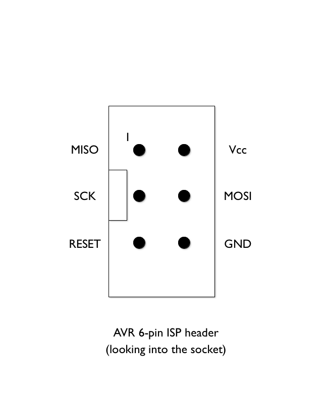
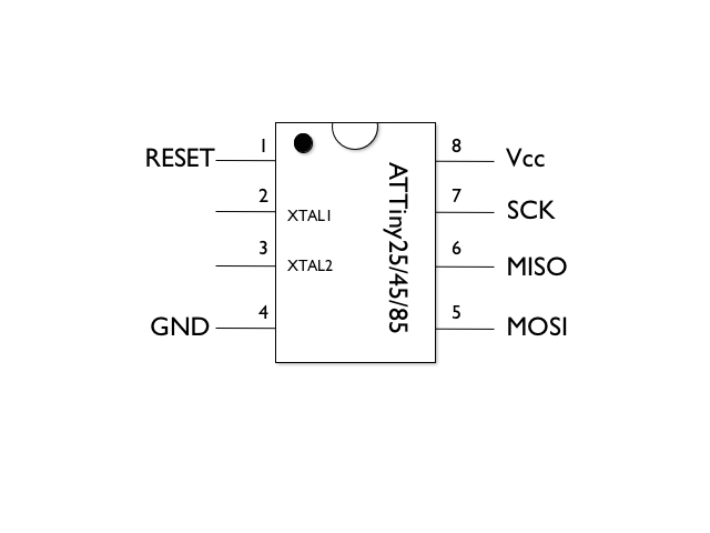
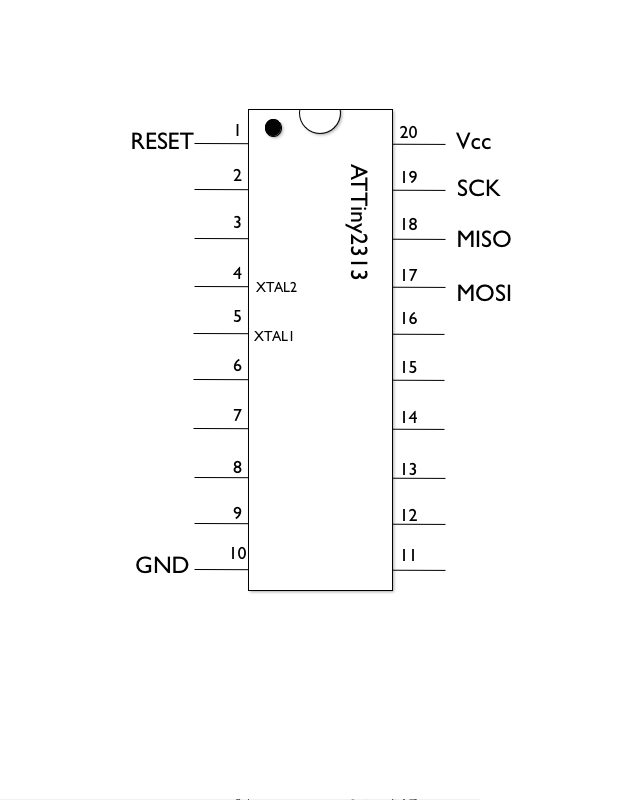
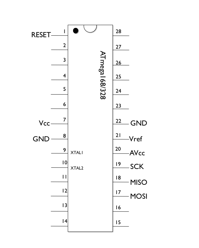
Saturday, February 4. 2012Thursday, February 2. 2012Even lazier ICSP programmingThe previous post discussed my gradual drift to using a dedicated ICSP programmer to reflash AVR chips. This post describes how to make useful ICSP slave boards, to make life easier yet. First up, some pinouts. I'm mostly interested in the 6-pin ICSP header, and the ATTiny85 (absolutely tiny, not many I/O pins), ATTiny2313 (a bit bigger, tiny memory, but built-in UART and more I/O pins), and ATmega328 (as used in Arduino). These are all drawn on a Mac in "Shapes", by the way. Another experiment, and it seems OK for basic diagrams, if a little buggy. £2.99 from the App Store.
I've only marked the pins that are important for ICSP. Connecting one of these up to an ICSP header is trivial - just connect the corresponding pin labels together between the ICSP header, and an IC socket. Notes:
Ah - but see how a lot of the pins are all in roughly the same place and order? Well, I wondered if you could connect up a single socket in such a way that it can be used to program any of these 3 chips? Luckily, we can! Continue reading "Even lazier ICSP programming" Thursday, February 2. 2012 |
Donate!
If you have found my site or software useful, please consider donating a small amount of money using the button below.
|