CategoriesCalendar
ArchivesQuicksearchSyndicationStatisticsLast entry: 2012-09-11 21:41
38 entries written
446 comments have been made
29 visitor(s) this month
1 visitor(s) today
0 visitor(s) online
Powered by
|
Tuesday, September 11. 2012Raspberry Rover part 2 : The Hardware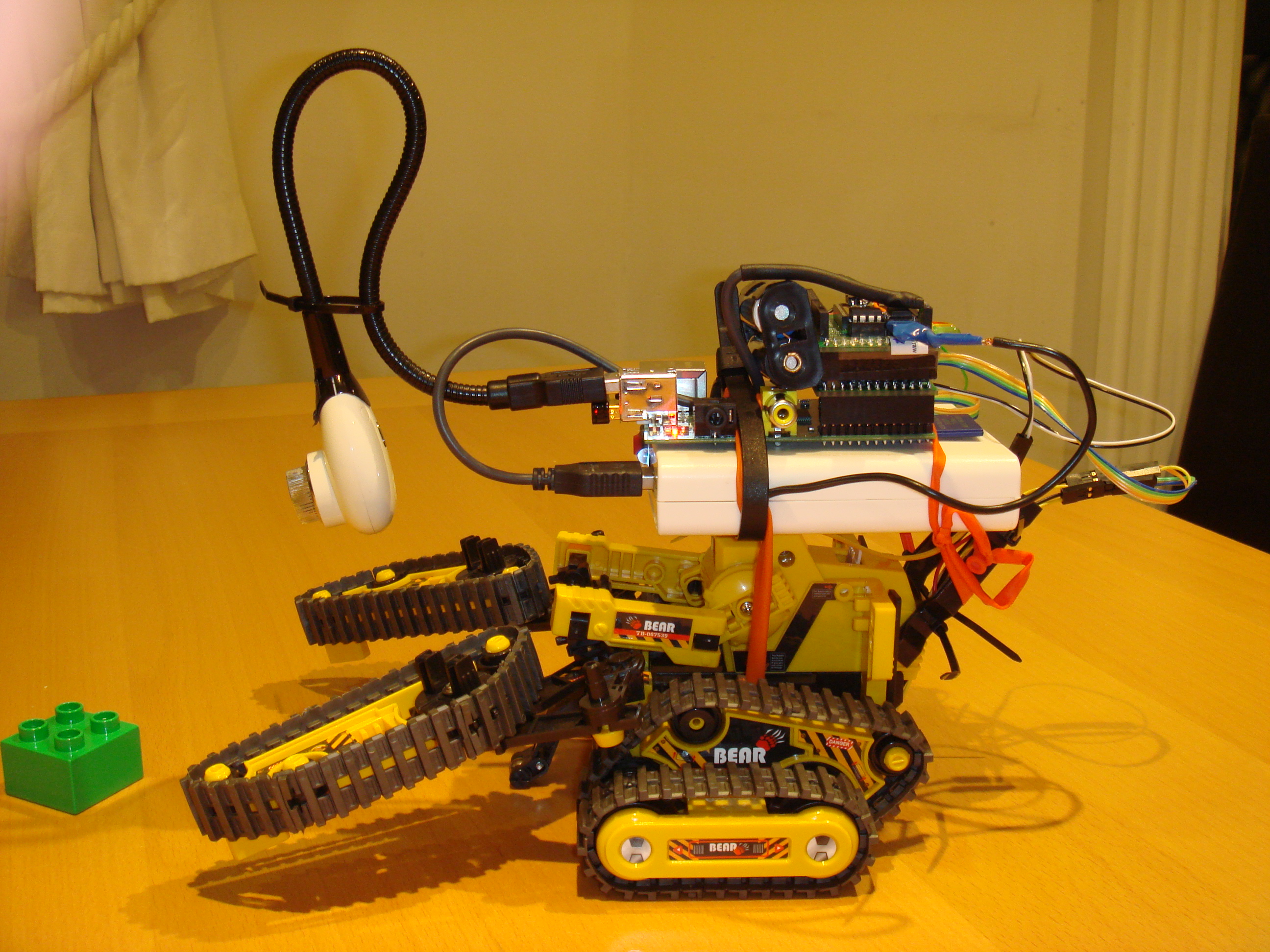 The new, improved, but uglier Raspberry Rover! A few months back, I posted about my prototype "Raspberry Rover" - and then I had to stop work on it for a while, because things were busy at work, and my part-time work on iFringe and FringeGuru were reaching their busiest time of the year with the Edinburgh Fringe Festival coming up. Recently I was able to pick it back up again, and fix a few of the snags that I'd come up against. It's now in a state where I feel able to share some of the lessons learnt. It's far from perfect, but it is functional with some clear ways forwards. This posting will deal with the hardware design, and I'll talk about software and further plans for the future later. The hardware consists of these main systems:
The chassis Cable ties and modelling balloons - the construction tools of kings. The Raspberry PiThe Pi makes for an excellent robot brain. It's cheap, fairly low power consumption, small, and has good connectivity and processing power for an embedded device. I found it very straightforward to add a cheap webcam (for vision) and tiny wifi adapter (Edimax EW-7811UN, which makes it easy to log into the robot while it's on the move). The GPIO header makes it easy to communicate directly with other hardware, exposing SPI, I2C, and various GPIO pins. These days, the default Raspbian kernel and Linux distro make it easy to interface directly with the GPIO hardware, which is great. Hardware Interface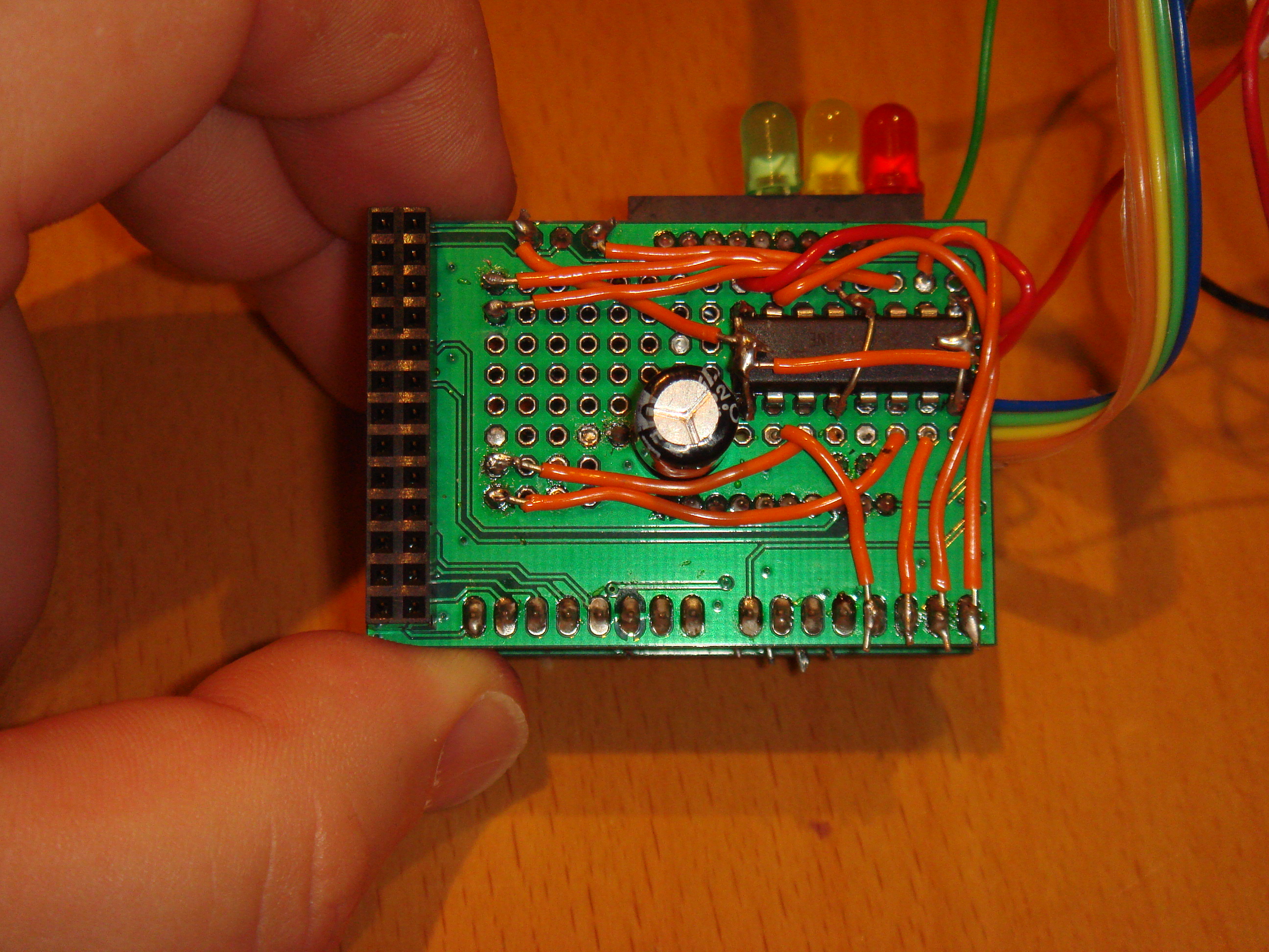 Plenty of space for a dual H-bridge motor controller. Placing a smoothing capacitor here on the board lines up nicely with blank space on the Raspberry Pi PCB, giving the board a bit more support and stability - otherwise it's supported entirely by the 26-way GPIO header. The prototyping area gave enough room to connect an SN754410 dual H-bridge motor controller. This was perfect for controlling the robot's motors, as it can be driven directly from the Pi's GPIO signals, and switches an optionally separate power supply to the motors. Sending one pin high drives the motor forwards, and another pin will drive it backwards. I connected very simply with one GPIO pin to each of the 4 direction control pins (2 for each motor), and the motor connectors directly to the motor output pins on the IC. Once I'd got things working with the basic 2 motors for movement, I decided to stack a second Slice of Pi on top of the first, so that I could add another H-Bridge driver (to control the auxiliary motor - for grabber, or forklift - connected exactly the same as the first), and also to add a couple of small microcontrollers, interfaced to the Pi over I2C.  Using stackable headers to make a stackable Slice of Pi board. This needs some care to make sure that components on the two boards don't physically clash with each other, but it works very well. I chose to use ATTiny85s, because I have a number of them lying around, they can be programmed via the Arduino tools, they're dirt cheap, they fit a surprisingly large amount of function into their titchy 8-pin package, and they can be run from a wide range of voltages (so I was able to connect them directly to the Pi's 3.3V rail, and not worry about level conversion). One of the ATTinies is currently designated as input (3 channels, 2 of them analogue-capable), and one as output (3 channels, currently driving LEDs directly).  LEDs mounted directly in a female header. These are controlled by an ATTiny85. There are a few advantages to using Tinies for IO:
A nicer choice yet would be to wire up an ATMega328 (the core of the Arduino), but that takes a lot more space on the prototyping board, and requires a handful of supporting components. The Tinies were more than sufficient for my needs. Where possible, everything was wired up with removable connectors - usually, taking a cue from the motor connectors, I used pin headers on the circuit board, with push connectors to connect to external components and power. Power supplyThis turned out to be the trickiest part to get right, although the initial design was very straightforward. In my post about powering a pi from batteries, I looked at a few ways to give the robot his own power supply. Eventually I settled on a battery box approach:
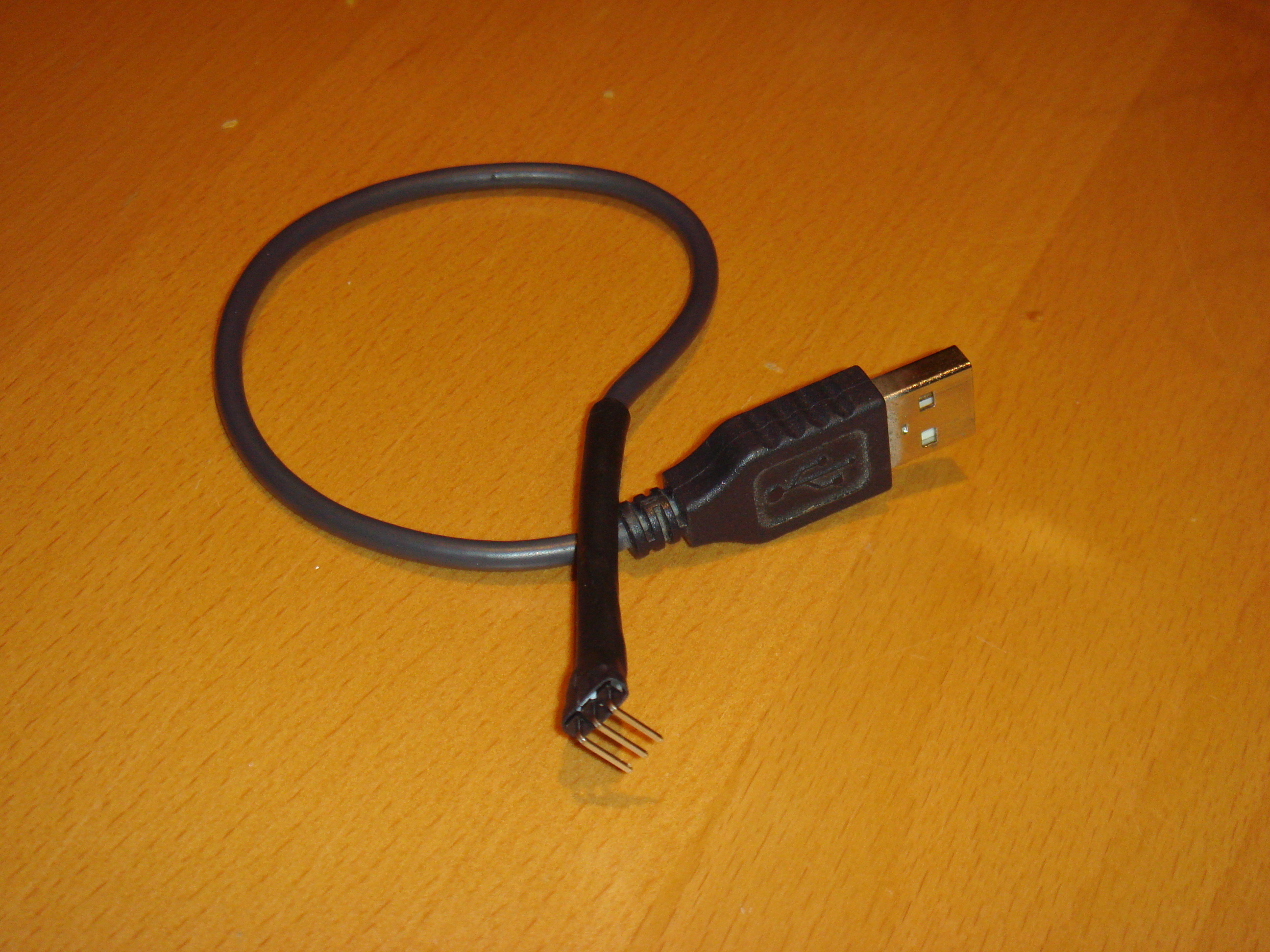 Custom USB power connector. Only 2 of the 3 pins are connected (5V and 0V). This connector fits nicely into the power header on the Slice of Pi board. As well as the standard 5V power output, I also hacked in a connection directly to the input voltage from the batteries to the power converter inside the box. This meant that I could directly read the current battery voltage using an analogue input on one of the ATTinies - giving me a charge level indication. As well as being quite cool to be able to get a battery level reading on the Pi, it also makes it possible to be able to automatically shut down the Pi if the battery level gets too low, avoiding damage to the batteries. In the end, due to problems with the motor power (see later), I also ended up mounting an additional standard battery pack, dedicated to supplying power to the motor. Problems, and their solutionsHere are a few of the snags I hit along the way, and the solutions I adopted.
In actionHere's a small video of the improved Rover in action.
Circuit diagrams[ Coming Soon ]Comments
Display comments as
(Linear | Threaded)
I love what you're doing, man! Keep it up!
 Comment (1)
#1
on
2012-09-19 16:24
great work ! i want to do this project. can you help me? how to your program
my gmail : legend1066@gmail.com Comment (1)
#2
on
2013-04-19 04:52
Hi Fanjita,
I came by your blog and the quality of content really grabbed my attention, so I thought I’d drop you a message. It’s great seeing so much Raspberry Pi stuff, and that’s what we’re into! I’m currently collaborating with Premier Farnell, a top electronics tech company, and we’d love to know if you’d be interested in mentioning PF and/or some of its products on your website. At the moment, we are able to provide bespoke content written by Premier Farnell’s very own tech copywriters at your request. Also, in the coming weeks we will also be expanding the scope of our collaborations to include things such as product testing, reviews, organising tech/electronics networking and events, and providing you with access to experts for Q&A. We could also potentially send products for giveaways on your site or offer exclusive discounts for your readership, which could stir up some interest. As I say, good content is available right now, but we can do the other stuff in the near future. Let me know what you think, and if you have any questions, fire away! Best, Joe Comment (1)
#3
on
2013-07-27 15:06
The author does not allow comments to this entry
|
Donate!
If you have found my site or software useful, please consider donating a small amount of money using the button below.
|
|||||||||||||||||||||||||||||||||||||||||||||||||
